The team uses as mobile platform the robot UTOPIA designed by LSA for research and educational purposes. The main application guiding the design was the football robot team, being the robot designed and implemented from scratch in order to be a suitable testbed for advanced coordinated control.
The range of research topic covered and large number of possible student application projects served assured the fullfilment of the above objectives (research and education).
The particular Robocup application, determined the system configuration, other UTOPIA configurations are used in different applications.
The first prototype was made in iron (the base mechanical structure weights about 35 Kg) and was used for the first tests with particular emphasis on the kicker design.
 |
 |
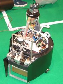
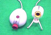
| Robot player (partial inside view) |
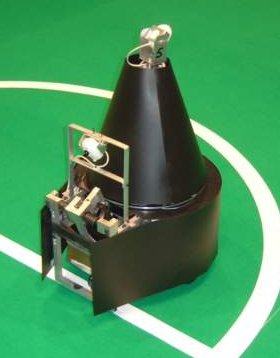
Robot player (covered) |
Particular attention was paid to the replication process, namely the choice of mechanical components and materials to reduce the replication costs and overall weight.
The actual team robots are made in lighter aluminum and have a redesigned mechanically modular kicker system. Currently we have 5 players.
System main characteristics
Aluminum Circular base (40 cm diameter) with rotating electromechanical kicker.
Weight: 20 Kg
Differential drive: 2 DC motors- Pittman GM9236 C534-R2
Power: 2 12V lead acid batteries.
ICP Nova 600 (AMD K6/2 266MHz, 24Mb Flash Disk, 32 Mb RAM) or
ICP Nova 7896FW (Celeron 900MHz, 24Mb Flash Disk, 128Mb RAM)
2 USB cameras (Philips PVC740K)
Mechanical Design
The mechanical design has taken in account the requirements necessary , in order to be able to execute complex manoeuvres and therefore not posing harsh limits on the control, navigation, or coordination subsequent developments.
The robot is constituted by three parts: a circular mobile base, a kicker connected to a structure that rotates around a central vertical axle and on top a computational an electronics module fixed relatively to the base with a pan mounted camera.
Base
The base contains two differential traction 24 V DC motors with optical encoders for motor control and vehicle odometry, two 12V lead acid batteries, the kicker rotation motor and the motor power drives (minimising the noise in other electronics components located on the top box).
Kicker
The kicker uses a DC motor and mechanical spring with a camber system and was designed to allow different kick strengths ranging from small passes to goal shots.
The rotary kicker allows the robot to perform complex manoeuvres and behaviors. It can intercept the ball smoothly (with the vehicle moving in one direction and the kicker simultaneously moving to control the ball without griping). There is the possibility of resolving ball deadlocks by the use of the kicker extra manoeuvrability. It can intercept the ball smoothly, rotate around the ball, resolve ball deadlocks, pass and shoot in diferent different directions The mechanical kicker design also allows the execution of different pass and shot movements. This is accomplished by kicking the ball in different positions with small impulse in full contact and strong kicks by letting the ball move some space away from the robot before kicking. The kicker is connected to a structure that rotates around central axle. This axle serves and the main support for the top module that is fixed with the base.
The system is mechanically modular, being possible to use the robot in different configurations, and in particular, different kicker designs can be used with the same base.
Hardware
Computational system
The main computational system is a Pentium based Single Board Computer (currently an ICP NOVA600 board with an AMD K6 /2 or NOVA7896 with Celeron) and IDE 24Mb Flash disk.
Axis control
The motor control is made in a custom designed multi-axis control board, comprising an FPGA and dedicated microcontroller. It communicates with the main CPU trough a PC104 connector (ISA bus). The PC104 form factor reduces size and it is a reliable connection system.
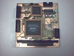
PC104 Axis control board
The board implements the low level control laws (currently 4 axis PID control at 2 KHz) for each axis (traction, kicker rotation and shot), receiving encoder information and providing a sign magnitude PWM control signal to the power drives.
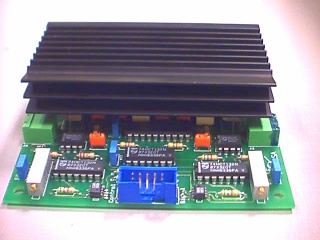
Power drives
The current amplifiers for the several motors are also a custom designed board with traditional H-bridge architecture and current sensing.
Vision System
The vision system is constituted by two USB cameras (Philips PVC740K with new wide angular lens), one mounted on a central pan unit and used mainly for long range vision and localisation and the other fixed to the kicker to be used for fine ball control.
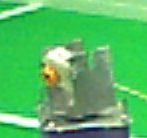
Two USB cameras used and pan unit
With this system, we can process image scenes at 30 fps with 70% of current CPU load. The main advantage of our vision system is the ability to implement intelligent vision strategies, which can use fast global analysis of the all image in order to decide where to conduct a more detailed one, focusing then in the important landmarks. An additional improvement is accomplished with the integration of the prediction the landmarks in the grabbed image or where the camera should point.
Communications
The robots communicate trough wireless ethernet radio modems : AirEZY 2405 from OTC Telecom
Other sensors
The robot has a custom developed ring of IR range measuring sensors (GP2D02) for short distance obstacle detection (up to 0.8m) and IR bumper sensors for ground marks detection and additional bumper sensing.
Software
The onboard computer runs a Linux operating from a flash disk, with a modular and hierarchic threaded software architecture.
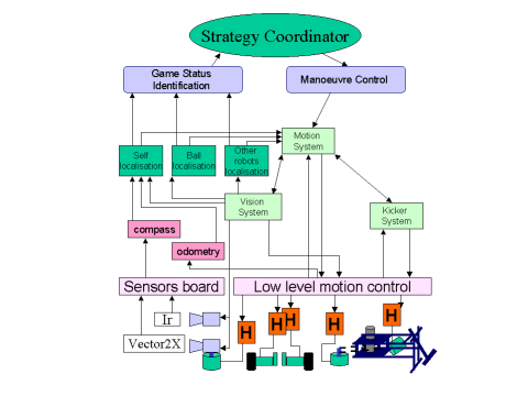 Software integration arquitecture