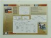
| Robot hardware architecture description: |
The architecture of the robot hardware is constituted basically by the next blocks: power, computer, sensors, actuation and communication. In the figure 1 is possible to visualize the interconnection between the blocks, in the form to constitute the architecture of the hardware:
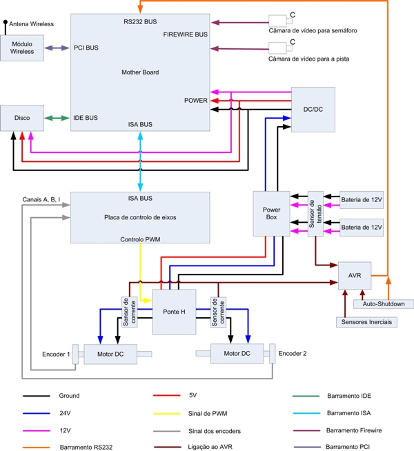
Like it illustrates the previous figure, several above-mentioned blocks previously are constituted by the hardware what step describing of pursuance. |
| |
|
| 1 - Axles control board |
| |
|
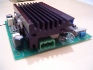
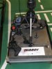
It is essentially a borad projected for the control of robot axles. It uses as a base, two highly versatile integrated circuits, of easy and quick configuration, being they:
- Microcontroller P89C51RD2.
- FPGA FLEX10 K10LC84-4, where is the principal characteristic, a high density, containing 10000 logical doors..
The microcontroller has access to the FPGA Ports or Xdata. This board has the possibility of communication of 8 bits, for ISA bus - format PC/104. It has all the pins of I/O available almost, both of the micro and of the FPGA, through tokens of 14 and 20 pins, as well as the token of the stack PC/104. It has an oscillator of 20 MHz and the possibility of extern interruption of the microcontroller. The principal function of this board is to do the control of the vehicle, with the information of the encoders, it communicates with the PC (where it is prosecuted to the whole information of the encoders and camera), receiving then values of speed and producing PWMs for the H-Bridges.
Figure 2 - Blocks diagram of the axles board. |
| |
|
| 2 - Power amplifiers board |
|
|
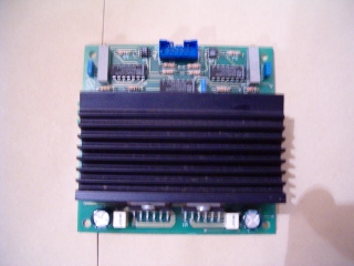
| The power amplifiers take the appropriate supply of energy to the motors, working like power drivers. They are constituted by two bridges H, able to be commands for the Axles bard through the use of impulses PWMs (Pulse With Modelation), what are turned into levels of tension supplied to the motors. |
| |
|
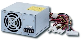
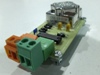
| 3 - Power and protection board |
|
|
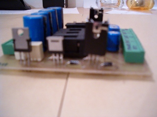
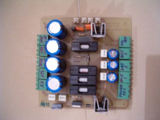
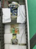
| The power and protection board, also called of Power Box does the distribution of energy for the remaining hardware. Another function of this board is the protection against overloads. It receives the energy coming from the batteries, being distributed. |
| |
|
| 4 - Cameras |
|
|
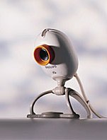
| The USB digital camera used was the model PCVC740K from Philips, due to the fact of the superior image quality of image. The maximum framerate supported by the camera with the resolution 640x480 pixeis is of 30fps. |
|
|
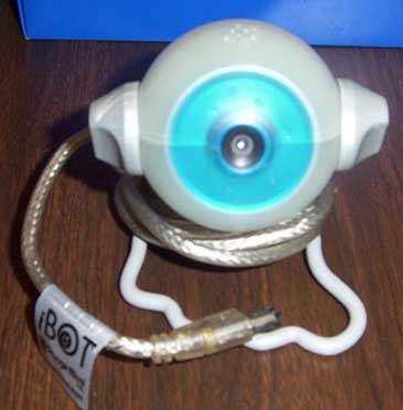
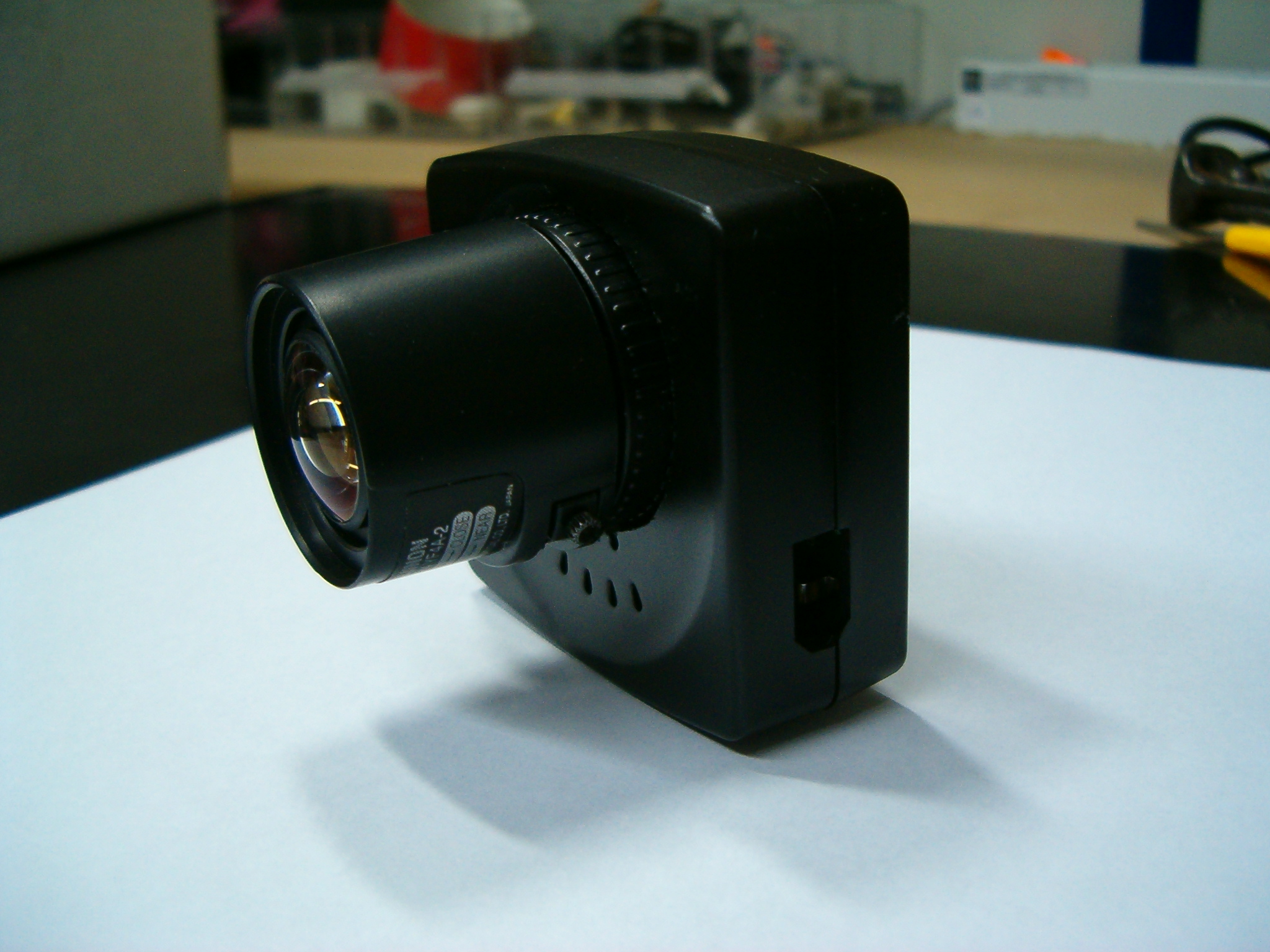
| The Firewire digital camera used was the model Orange Micro iBOT Pro. The maximum framerate supported by the camera with the resolution 640x480 pixeis is of 30fps. |
|
|
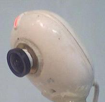
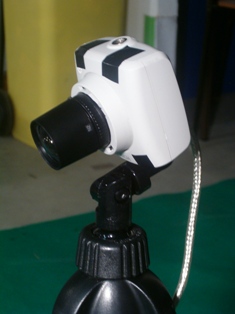
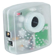
| The Firewire digital camera used was the model Unibrain Fire-i. The maximum framerate supported by the camera with the resolution 640x480 pixeis is of 30fps. |
| |
|
| 5 - Computer |
|
|
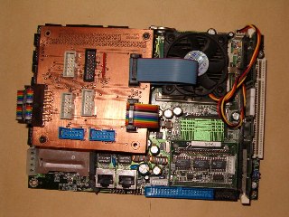
The computer used it's composed of:
- mother-board IPC NOVA 7896FW (SpeedRunner)
- Harddisk 2.5 40GB (SpeedRunner)
- Processor P3 Tualatin at 1.26GHZ
|
- mother-board Ibase MB820 (BigRunner)
- Harddisk 3.5 40GB (BigRunner)
- Processor P4 at 3Ghz
|
| |
|
| 6 - DC/DC Converter |
|
|
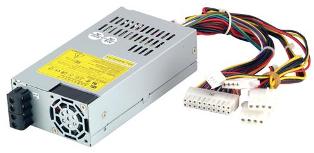
| The DC/DC converter is to supply power to the motherboard, hard disk with the expected tensions of 5V and 12V. |
| |
|
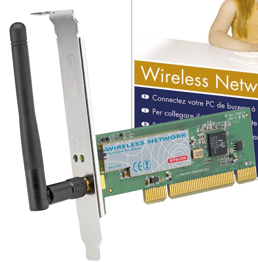
| 7 - Wireless |
|
|
| The wireless connection to the robots is done using SITECOM WL-115 PCI boards of 54MB. |
| |
|
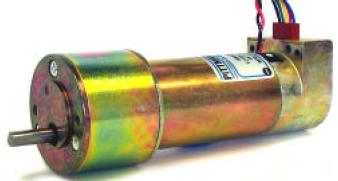
| 8 - DC Motors |
 |
 |
| The continuous current motors used in the robot SpeedRunner are the PITTMAN GM9236C34-R2. These motors already have desmultiplication box of 5,9. These motors have the peculiarity of having opticial encoders, for the case these are of 3 channels and resolution of 512 ticks for revolution of the optical disc. |
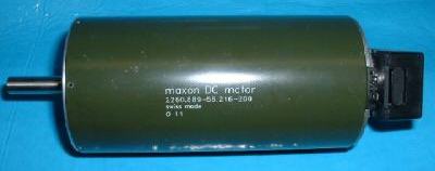
The continuous current motors used in the robot BigRunner are the Maxon. These motors already have desmultiplication box of ??. These motors have the peculiarity of having opticial encoders, for the case these are of ?? channels and resolution of ?? ticks for revolution of the optical disc. |
| |
|
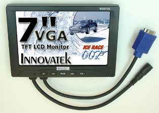
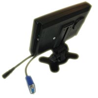
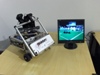
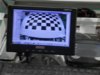
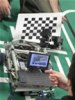
| 9 - TFT Monitor |
|
|
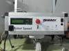
| To help in the visualization of the state of the robot, there was added a TFT monitor Innovatek IN-007VG 7 ". |
| |
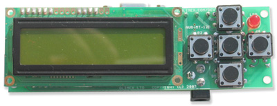
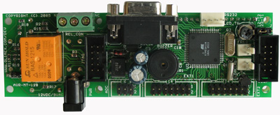
| 10 - Monitor and control board |
|
|
| To monitor the inertial sensors, tensions and currents of the robot and control additional features like disconnecting the PC when a determined tension of the batteries was reached there is used the development board AVR-MT-128. |
| |
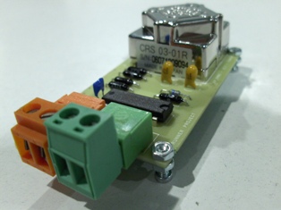
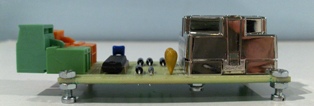
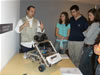
| 11 - Inertial sensors board |
|
|
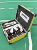
| To have acess to the information of the inertial sensor the hardware of the photos above was developed with the CRS-03 from Silicon Sensing Systems.. |
| |
|